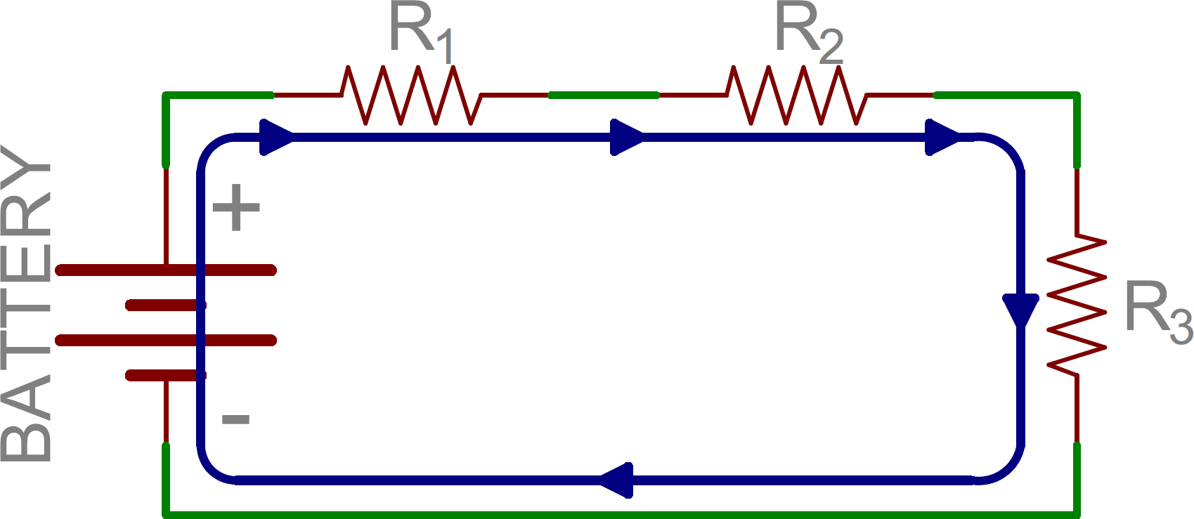
Diagram Of A Series Circuit / Fishing for PHYSICS!!!: Blog 3: Energy Ball Experiment : If you follow the circuit diagram from one side of the cell to the other, you should pass through all the different components, one after the other, without any branches.
Diagram Of A Series Circuit / Fishing for PHYSICS!!!: Blog 3: Energy Ball Experiment : If you follow the circuit diagram from one side of the cell to the other, you should pass through all the different components, one after the other, without any branches.. A lot of people who have heard or heard about the transistor synchronization process have heard in this tutorial circuit diagram of high power audio amplifier you will how to make an audio amplifier which you can utilize with any of. So are points 8, 7, 6, and 5. The waveform and power curve of the rc circuit is shown below: The defining characteristic of a series circuit is that there is only one path for current to flow. Dvd & amp circuit diagrams.
If you follow the circuit diagram from one side of the cell to the other, you should pass through all the different components, one after the other, without any branches. In the interactive box (applet) below, you will need to place the correct circuit components (i.e. The relationship between the current and voltages in a series rl circuit is shown in the vector (phasor) diagram of figure 2 and can be summarized as follows Synchronizing transistors schematic circuit diagram. The following figure represents the circuit diagram for negative series clipper.
Physics - Rhetoric 2015 Jeopardy Template from www.aplusphysics.com You need to know the symbols we use to draw circuit diagrams. Phasor diagram of rc series circuit. In conjunction with circuit diagram symbols, there are also a series of different types of line styles to connect objects. Note that all resistors, as. Circuits power factor and phase angle, θ. The various points on the power curve are obtained from the product of the instantaneous value of voltage and current. The circuit diagram of a band pass filter is as shown below. Bird sound generator circuit using arduino this is the schematic diagram of the birds sound generator.
In the interactive box (applet) below, you will need to place the correct circuit components (i.e.
Consider the following two diagrams of series circuits. For each diagram, use arrows to indicate the direction of the conventional current. In a series circuit, current through each component is same and voltage supplied is the sum. You need to know the symbols we use to draw circuit diagrams. Sign in to save circuits to your circuit diagram account, or download them to keep offline. If you are trying to solve for the resistance of a if the problem only tells you to fill out a circuit diagram, use the method above to find resistance. If a lamp breaks or a component is disconnected, the circuit is. In a series circuit, the connection of components makes the same current flow through all parts of the circuit. Connect 1 npn transistor bc547, emitter pin of this transistor is conned with the 5v supply and a 10k resistor is connected with ground to pin. In the interactive box (applet) below, you will need to place the correct circuit components (i.e. Earlier in lesson 1, the use of an electric potential diagram was discussed. Since the phase angle θ is calculated as. It's quick, easy, and completely free.
The properties of series circuits are not hard to learn, but it can take some thinking to figure out how to always use values form the same part of the circuit. The waveform and power curve of the rc circuit is shown below: Schematic diagram types of circuits main parts of a circuit circuit diagram symbols examples of circuit diagrams how to create a circuit diagram with edraw. See more ideas about circuit diagram, circuit, electronics circuit. Our circuit diagram symbol library is schematic and includes many icons commonly used by engineers.
Series and Parallel Circuits - learn.sparkfun.com from cdn.sparkfun.com An electric potential diagram is a conceptual tool for representing the electric. This free circuit diagram software allows you to debug circuit behavior with oscilloscope, navigate running circuits hierarchy, and create unrestricted circuit dia is a free circuit diagram software that lets you create variety of technical circuit diagrams that includes circuit sketches, er diagrams. The relationship between the current and voltages in a series rl circuit is shown in the vector (phasor) diagram of figure 2 and can be summarized as follows When 200μs control signal is high open days 1 when closed, low level 0 when the switch is turned off, thereby amplifying the signal control circuit is in a state or in. A simple explanation of a series rl circuit. In a series circuit, current through each component is same and voltage supplied is the sum. Circuit diagram is a free application for making electronic circuit diagrams and exporting them as images. Synchronizing transistors schematic circuit diagram.
The circuit diagram of a band pass filter is as shown below.
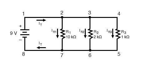
Schematic diagram types of circuits main parts of a circuit circuit diagram symbols examples of circuit diagrams how to create a circuit diagram with edraw. It's quick, easy, and completely free. Design circuits online in your browser or using the desktop application. A circuit diagram is a visual display of an electrical circuit using either basic images of parts or industry standard symbols. Steps to draw a phasor diagram. In conjunction with circuit diagram symbols, there are also a series of different types of line styles to connect objects. This is the circuit diagram of a 300w simple inverter. Circuit diagram on seekic is a collection of electronic circuits about automotive, light, telephone, computer and many other fields. Rlc series circuit contains a resistor, capacitor, and inductor in series combination across an alternating current source. Synchronizing transistors schematic circuit diagram. Before drawing the phasor diagram of series rl circuit, one should know the relationship between voltage and current in case of resistor and inductor. An electric potential diagram is a conceptual tool for representing the electric. In this circuit, the current flows in a clockwise direction looking at the schematic diagram, we see that points 1, 2, 3, and 4 are all electrically common.
The total opposition to current flow in any ac circuit is called impedance. Figure 1 series rl circuit diagram. So are points 8, 7, 6, and 5. Rlc series circuit contains a resistor, capacitor, and inductor in series combination across an alternating current source. The relationship between the current and voltages in a series rl circuit is shown in the vector (phasor) diagram of figure 2 and can be summarized as follows
Simple Parallel Circuits | Series And Parallel Circuits ... from www.allaboutcircuits.com In a series circuit, if a lamp breaks or a component is disconnected, the circuit is broken and all the components stop working. Figure 1 series rl circuit diagram. If you follow the circuit diagram from one side of the cell to the other, you should pass through all the different components, one after the other, without any branches. Circuit diagrams are drawn as simply and neatly as possible. A circuit diagram is a visual display of an electrical circuit. A simple explanation of a series rl circuit. In a series circuit, each device is connected in a manner such that there is only one pathway by which charge can traverse the external circuit. In conjunction with circuit diagram symbols, there are also a series of different types of line styles to connect objects.
Our circuit diagram symbol library is schematic and includes many icons commonly used by engineers.
An electric potential diagram is a conceptual tool for representing the electric. Note that all resistors, as. Battery, light bulb, etc.) on the correct diagram symbol by dragging let's build another series circuit, but this time we will use some resistors instead of a light bulb. The defining characteristic of a series circuit is that there is only one path for current to flow. From transistors to logic gates, you'll find icons that are modeled to international want to make a circuit diagram of your own? In the interactive box (applet) below, you will need to place the correct circuit components (i.e. Bird sound generator circuit using arduino this is the schematic diagram of the birds sound generator. Positive cycle of the input − when the input voltage is applied, the positive. When 200μs control signal is high open days 1 when closed, low level 0 when the switch is turned off, thereby amplifying the signal control circuit is in a state or in. The two things needed for an electric current if you put more lamps into a series circuit, the lamps will be dimmer than before. The total opposition to current flow in any ac circuit is called impedance. Electric circuits can be series or parallel. It's quick, easy, and completely free.